Linkage Design Inputs & Outputs

Inputs
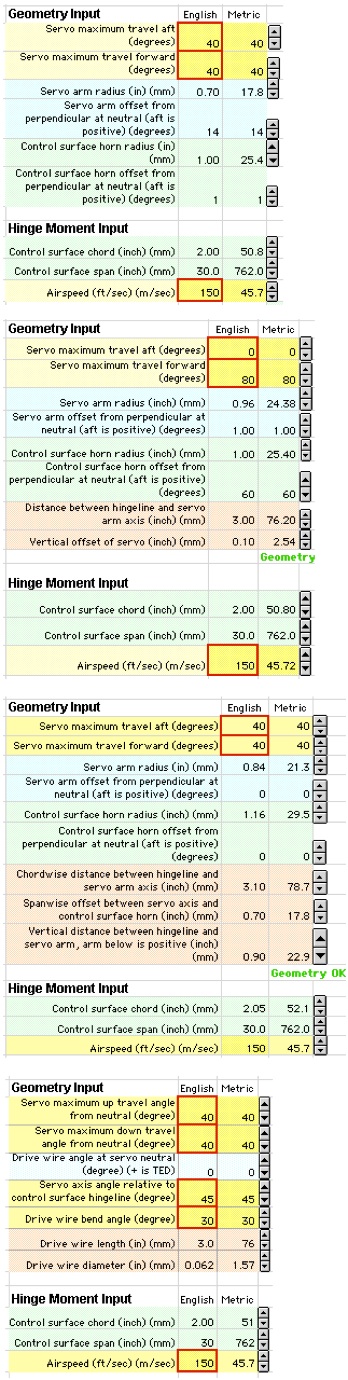
Linkage Design inputs are numeric values that describe the geometry of the servo and control surface arrangement. There is also an input for airspeed so that servo torque can be approximately calculated.
The inputs are made using the little up/down arrows. These incrementally adjust the value. A single click makes a small change. If you hold the arrow down, the value changes quickly.
The typical process is to start by making a guess at all the values (a preliminary setup) and then refining the setup using the plots and output blocks. The data entry arrows work especially well in the fine-tuning phase.
The input values are quantified simultaneously in English and metric units - the arrows adjust both at the same time.
Input for Long Pushrod
Input for Long Pushrod is easy. Just define the servo and control horn setup so that the program can figure out the control surface motion. Also define the control surface dimensions and airspeed so that the program can estimate servo torque.
It is a convention of the program that the control surface is faired (zero deflection) when the servo deflection is zero. This way it is easy to set up for equal deflection (elevator) or asymmetric deflection (flaps) or some combination (flaperons).
Input for Short Pushrod
Input for the Short Pushrod setup is nearly the same as for the Long Pushrod setup except that now the program needs to know where the servo is relative to the control surface. These values are reflected immediately in the picture of the arrangement.
The program uses this extra information to make a precise calculation of the control surface location, taking into account the variation in pushrod angle that arises from the proximity of the servo and control surface.
Input to Perpendicular Axis Pushrod
These inputs are again in the same format as Long Pushrod except that inputs are required to define the relative location of servo.
Rotary
The inputs for the Rotary arrangement are different from the others, but the same in concept.
An additional input is the drive wire length and diameter. This is an important consideration for this arrangement in that it strongly influences the rigidity of the system. The program calculates the approximate flexure of the drive wire and the resultant control surface offset as a result of aerodynamic load. This helps the designer determine the wire diameter.
Outputs
Results from the calculations are shown immediately in several different ways. First and foremost, there is a drawing of the setup that changes in response to the inputs. This is shown on the "drawings" page.
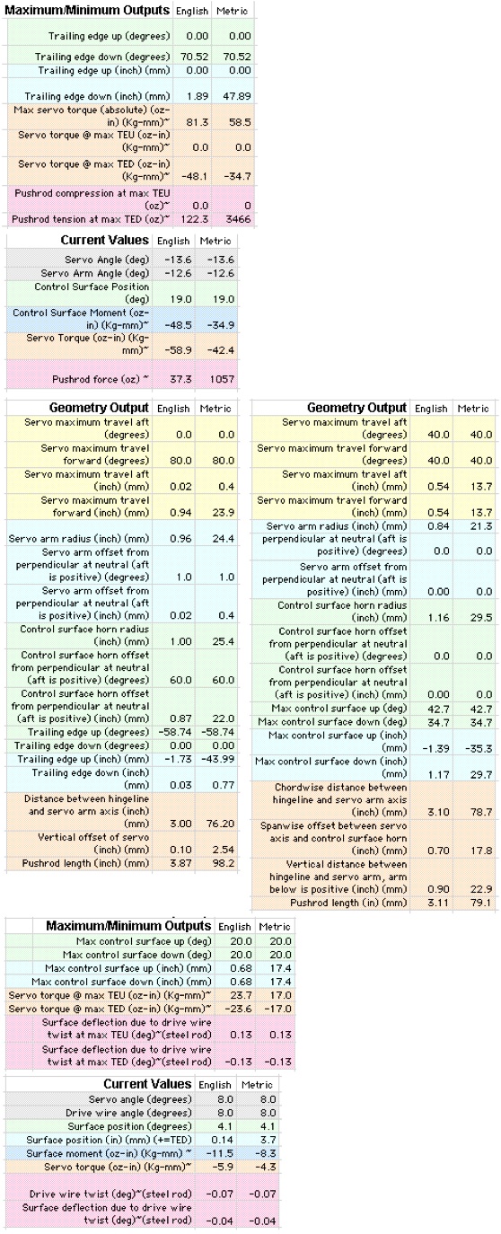
A second form of output, a numeric output, is shown on this page. It is broken into three blocks. The first, "Maximum / Minimum Outputs", defines the limits of the control surface deflection at maximum and minimum servo deflection and at an intermediate point if this results in greater surface deflection. This allows the modeler to set up the geometry per the airplane designer's instructions or to his own liking.
The program also provides approximate maximum servo torque as well as pushrod forces. This enables choosing a suitable servo and pushrod design.
The second numeric output reports the "Current Values". The graphic drawing of the servo setup is provided with a slider bar. This slider controls the deflection of the servo - the servo and control surface move in response to the slider bar. As you move the system, the "Current Values" data block reports the key angles, torques and forces on the system.
The third numeric output block reports the "Geometry Output". This is a comprehensive report of the information that you need to set up your model in the shop or to lay it out on the drafting board or CAD system.
A third form of output is provided in a series of plots. These can provide additional, rapid insight into the design of the system. These are shown on the "plots" page.
Maximum/Minimum Outputs
These outputs are reported in the same format for all three pushrod setups.
Control surface deflections are reported in terms of degrees and linear dimensions.
All outputs are reported in English and metric units.
Current Values
Current values are also reported in the same format for all three pushrod setups.
Geometry Output
Geometry output gathers up all the key information in one place so that you can print it out and use it in the shop or in the design drafting process.
All three pushrod programs use the same geometry output format, with small variations. The output for Short Pushrod and Perpendicular Axis Pushrod are shown here.
All of the key angular dimensions are also reported in terms of linear deflection to make setup in the shop easier.
The Rotary program does not have a geometry output block because in its case the input block is the output block (!)
Maximum/Minimum Outputs for Rotary
The Rotary outputs are similar to the others except that it adds information on deflection due to system flexibility.
Current Values for Rotary
These are reported in a similar format to the max/min outputs.